A-126-2exp Frequency Shifter Expander
Doepfer
Regular price
$470.00 HKD
Sale
Module A-126-2 is a fully analog frequency shifter for audio signals. A frequency shifter is an audio processing unit that shifts each frequency of the incoming audio signal by the same frequency. If the shifting frequency is e.g. 200Hz an incoming audio frequency of 1000 Hz becomes 1200 Hz, 2000Hz becomes 2200 Hz, 3000 Hz becomes 3200 Hz and so on. Pay attention that this is different from pitch shifting where all frequencies are shifted proportional (e.g. 1000>1200Hz, 2000>2400Hz, 3000>3600Hz) !
The frequency range of the internal quadrature VCO is about 8 octaves (about 20Hz ... 5kHz). If required an external quadrature VCO can be used.
The module is equipped with these controls, inputs and outputs:
-
Frequ. 1: first manual control of the shifting frequency (factory setting: coarse, range about 20Hz - 5 kHz)
-
Frequ. 2: second manual control of the shifting frequency (factory setting: fine)
-
by means of internal jumpers the sensitivity of Frequ.1 and 2 can be swapped (i.e. Frequ.1 = fine and Frequ.2 = coarse)
-
the relation between coarse and fine control is about 25:1 (corresponding to about 8 octaves to 1/3 octave)
-
FCV In (socket) and FCV (small control without knob): control voltage input with attenuator for the external voltage control of the shifting frequency
-
Mix: manual control of the up/down shift panning unit, fully CCW = down shift, fully CW = up shift, in between a mixture of down and up
-
Mix CV In (socket) and Mix CV (small control without knob): control voltage input with attenuator for the mixing unit for external voltage control of the up/down mixing
-
Audio In (socket), Level (small control without knob) and Overload (LED): audio input with attenuator, typ. audio in level = 1Vpp, the level control has to be adjusted so that the overload LED just begins to light up a bit, when the LED is fully on clipping/distortion occurs, when the LED is permanently off the input level is too low and the signal-to-noise ratio increases
-
Audio Out (socket): audio output of the frequency shifter
-
Squelch (small control without knob): controls the squelch function: fully CCW (Env.) the output VCA is controlled by the envelope signal, which is derived from the audio input signal, fully CW (open) the output VCA is permanently open (no squelch function), in between the squelch intensity can be adjusted
-
Quadrature VCO Outputs (sockets Sin and Cos): outputs of the internal quadrature oscillator, about 12Vpp level (+6V/-6V)
-
Ext. Inputs Sin and Cos (sockets): required when an external quadrature VCO (e.g. A-143-9 with a wider frequency range or A-110-4 with thru zero feature or A-110-6 with different waveforms) is used instead of the internal quadrature VCO, the levels of the external VCO should be about 10Vpp (8...10Vpp are OK) and the signals have to be symmetrical around zero Volts, the sockets are normalled to the internal quadrature VCO (i.e. the sockets are equipped with switching contacts that interrupt the internal connection as soon as a plug inserted)
-
VCA ext. CV (socket): used when an external control voltage (e.g. from an envelope generator) should be used to control the output VCA instead of the internal squelch unit, the socket is normalled to the output of the squelch control (i.e. the socket is equipped with a switching contact that interrupts the internal squelch connection as soon as a plug inserted). From about +8V external control voltage the VCA is fully open.
-
Internal terminals (single pin headers for the connection to the expansion module A-126-2Exp or own DIY applications):
-
envelope follower output
-
dome filter output 1
-
dome filter output 2
-
ring modulator 1 output
-
ring modulator 2 output
-
Up shift output
-
Down shift output
-
Audio Input #2 for feedback effects (available only from version 2 of the module early in 2022)
-
GND
-
Technical details:
The analog frequency shifter is based on these trigonometric equivalences:
-
sin(a)*sin(b) = cos(a-b) - cos(a+b)
-
cos(a)*cos(b) = cos(a-b) + cos(a+b)
Building the sum and difference of these formulas one obtains:
-
Sum: sin(a)*sin(b) + cos(a)*cos(b) = 2 cos(a-b)
-
Difference: sin(a)*sin(b) - cos(a)*cos(b) = -2 cos(a+b)
When (a) in these formulas is treated as an audio signal and (b) as a sine signal it's possible to derive an up or down frequency shift with the frequency amount (b) for the audio signal (a). To realize the formulas these electronic circuits are required:
-
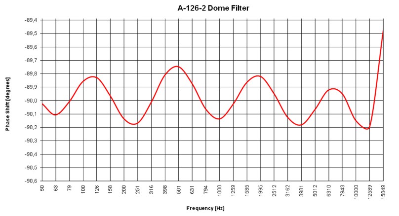
A phase shifter that shifts all frequencies of the audio signal (a) by 90 degrees (sine and cosine are the same signals but with 90 degrees phase difference). Such a circuit can be realized by means of a so-called Dome filter (named after the inventor Robert Dome). The circuit is made in principle with several allpass filters which have to be dimensioned very carefully so that the phase shift for all relevant frequencies is as close as possible to 90 degrees. In the A-126-2 a 12-stage Dome filter is used which is made with close-tolerance parts (resistors with 0.1% tolerance and capacitors with 1% tolerance). That way the time killing adjustment of many trimming potentiometers (with mutual influence) is avoided.
-
The Dome filter of the A-126-2 generates 90 degrees phase shift with less than 0.3 degrees error over a frequency range of about 50 Hz to 14 kHz.
-
A quadrature oscillator (i.e. an oscillator with simultaneous sine and cosine output, similar to the already existing modules A-143-9 or A-110-4
-
two multipliers: in the A-126-2 two ring modulators are used for this job, with optimal adjustment the feedthrough of the quadrature VCO is about -54dB (according to typically 10mVpp feedthrough compared to 5Vpp max. signal level) without squelch function. The feedthrough amount depends upon the shifting frequency and increases with the frequency.
-
a summing unit
-
a subtracting unit
Beyond that the A-126-2 has some special features:
-
An envelope follower is used to derive an envelope signal from the audio signal. It generates a voltage that corresponds to the current level of the audio signal. A comparator is used to drive an LED which works as overload display. In addition the envelope signal is used to control a VCA which works as a squelch unit.
-
The up and down outputs are internally connected to the inputs of a voltage controlled crossfader. That way the relation between up and down signal can be controlled manually and by means of an external control voltage.
-
The module is fully DC coupled so that even very low frequency shifts are possible (with external quadrature VCO)
-
Because of the DC coupling one has to pay attention that the incoming audio signal and possibly external sine/cosine signals are exactly zero-symmetrical. Otherwise artefacts will occur (e.g. loud feedthough of the sine/cosine signals at the output because of a DC offset of the incoming audio signal). In case of doubt AC coupled modules should be inserted in the signal paths.
-
The module is complete built in thru-hole technique (including the dome filter), no smt.
-
Because of the 100% analog circuitry the module requires a few minutes heat-up time until all parameters are stable
-
In the factory the module is adjusted for power supply voltages of exactly +12.0V und -12.0V. If the actual supply voltages differ from these values (e.g. 11.5V or 12.5V) the module may have to be readjusted.
The following document explains the positions of the internal pin headers (e.g. for the connection to the expander module A-126-2Exp), the positions and functions of the trimming potentiometers and the adjustment procedures: A126_2_internal.pdf
This document explains also the connection between main module and the expansion module. The connections are established by so-called Arduino cables. They are included with the expansion module.
The sketch below shows the internal structure of the module in detail and the phase shift of the dome filter.
Below you find also some patch examples.
Notes concerning the difference between version 1 and 2 of A-126-2
The only difference between version 1 and 2 of the A-126-2 is that version 2 is equipped with an additional internal pin header which offers a second audio input in combination with the expander module. When the delivery of version 1 started (September 2021) it was not yet sure if an expander module will be available or not. That's why this additional output is not availabe in version 1 because the decision for the expander module has been made end of 2021 (i.e. 3 months after the delivery of version 1).
The meaning of the additional audio input 2 is not that important as it may seem at first sight. It has been just added because the expander module had an eighth unused socket. The feedback feature is also possible with version 1 of the A-126-2. Below you find two patch examples in this regard:
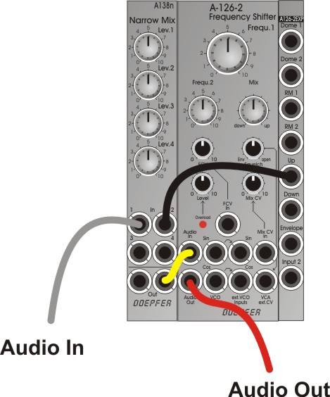
The first example shows a patch that can be used for both versions. It uses an external mixer A-138n to realize the feedback function. The mixer is used to mix the audio input signal with one of the outputs of the A-126-2. As the A-138n still has two unused inputs these can be used e.g. for multiple feedback (i.e. using two different outputs - e.g. Up and Down or Up and RM2 - simultaneously for feedback, or as a mixer for two audio inputs for the frequency shifter).
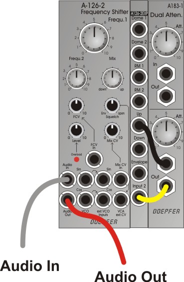
The second example shows a feedback patch for version 2. To be able to adjust the feedback amount at least an attenuator/amplifer (e.g. A-183-1, A-183-2, A-183-3) is required. But this patch does not offer as many possibilities as the version with the mixer A-138n. That's why we recommend the first patch also for version 2 of the A-126-2. And the price difference between A-183-1 and A-138n is very little.
Versions 1 and 2 can be distinguished by means of the PC board silk screen printing or the available pin headers: the silk screen printing of the lower board says "BOARD A VERSION 2" near the bus connector. And the pin header JP17 (AUDIO IN 2) is available only for version 2.
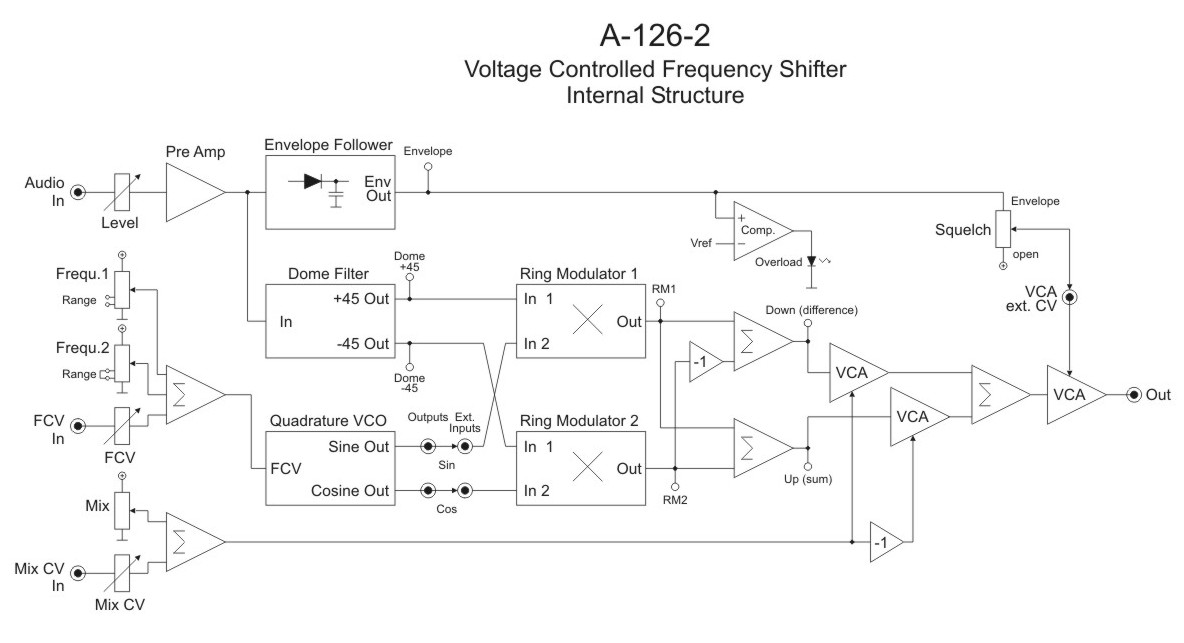
(der zweite Audio-Eingang der Version 2 fehlt noch ist in diesem Schaltbild / the second audio input of version 2 is not yet shown in this schematics)
|
|
|
|
|
A-126-2 Feedback Example 1 The mixer A-138n is used to add one of the output signals (e.g. Up, Down, RM1, RM2 or the Audio Output) to the input signal. |
A-126-2 Feedback Example 2 The attenuator A-183-1 is used to attenuate one of the output signals (e.g. Up, Down, RM1, RM2 or the Audio Output) and add it to the input signal via the "Input 2" socket of the expander module. . |
|
|
|
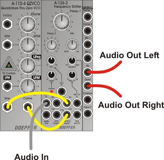
A-126-2 Stereo Example Instead of the Audio Output of the main module the Up and Down outputs of the expander module are used in this example as audio signals for left and right (even RM1/RM2 or Dome 1/2 may be used) |
Breite/Width: 8 TE / 8 HP / 40.3 mm
Tiefe/Depth: 60 mm (gemessen ab der Rückseite der Frontplatte / measured from the rear side of the front panel)
Strombedarf/Current: +80mA (+12V) / -70mA (-12V)

